1-35
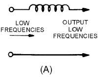
View (A) of figure 1-16 shows the electrical construction of a low-pass filter with an inductor
inserted in series with one side of a line carrying both low and high frequencies. The opposition offered
by the reactance will be small at the lower frequencies and great at the higher frequencies. In order to
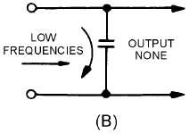
divert the undesired high frequencies back to the source, a capacitor must be added across the line to
bypass the higher frequencies around the load, as shown in view (B).
Figure 1-16A.—Components of a simple low-pass filter.
Figure 1-16B.—Components of a simple low-pass filter.
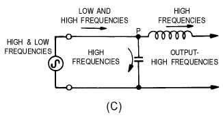
Figure 1-16C.—Components of a simple low-pass filter.
The capacitance of the capacitor must be such that its reactance will offer little opposition to
frequencies above a definite value, and great opposition to frequencies below this value. By combining
the series inductance and bypass capacitance, as shown in view (C), the simplest type of low-pass filter is
obtained. At point P, a much higher opposition is offered to the low frequencies by the capacitor than by
the inductor, and most of the low-frequency current takes the path of least opposition. On the other hand,


