3-24
coupling part of the output signal (Eout) back to the inverting (-) input of the operational amplifier. R1 and
R2 act as voltage divider that allows only a part of the output signal to be applied as feedback (Efdbk).
Figure 3-16.—Noninverting configuration.
Notice that the input signal, output signal, and feedback signal are all in phase. (Only the positive
alternation of the signal is shown.) It may appear as if the feedback is regenerative (positive) because the
feedback and input signals are in phase. The feedback is, in reality, degenerative (negative) because the
input signals is applied to the noninverting input and the feedback signal is applied to the inverting input,
(Remember, that the operational amplifier will react to the difference between the two inputs.)
Just as in the inverting configuration, the feedback signal is equal to the input signal (for all practical
purposes). This time, however, the feedback signal is in phase with the input signal.
Therefore:
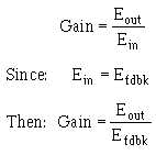
Given this condition, you can calculate the gain of the stage in terms of the resistors (R1 and R2).
The gain of the stage is defined as:
The feedback signal (Efdbk) can be shown in terms of the output signal (Eout) and the voltage divider
(R1 and R2). The voltage divider has the output signal on one end and ground (0 volts) on the other end.
The feedback signal is that part of the output signal developed by R1 (at point A). Another way to look at
it is that the feedback signal is the amount of output signal left (at point A) after part of the output signal


