3-19
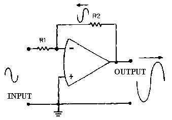
Figure 3-13.—Inverting configuration.
At this point it is important to keep in mind the difference between the entire circuit (or operational
circuit) and the operational amplifier. The operational amplifier is represented by the triangle-like symbol
while the operational circuit includes the resistors and any other components as well as the operational
amplifier. In other words, the input to the circuit is shown in figure 3-13, but the signal at the inverting
input of the operational amplifier is determined by the feedback signal as well as by the circuit input
signal.
As you can see in figure 3-13, the output signal is 180 degrees out of phase with the input signal. The
feedback signal is a portion of the output signal and, therefore, also 180 degrees out of phase with the
input signal. Whenever the input signal goes positive, the output signal and the feedback signal go
negative. The result of this is that the inverting input to the operational amplifier is always very close to 0
volts with this configuration. In fact, with the noninverting input grounded, the voltage at the inverting
input to the operational amplifier is so small compared to other voltages in the circuit that it is considered
to be VIRTUAL GROUND. (Remember, in a closed-loop operation the inverting and noninverting inputs
are at the same potential.)
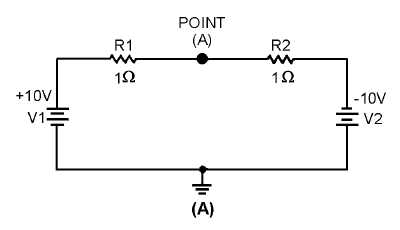
Virtual ground is a point in a circuit which is at ground potential (0 volts) but is NOT connected to
ground. Figure 3-14, (view A) (view B) and (view C), shows an example of several circuits with points at
virtual ground.
Figure 3-14A.—Virtual ground circuits.


