1-21
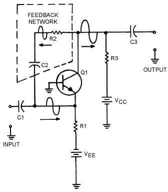
The feedback network in this amplifier is made up of R2 and C2. The value of C2 should be large so
that the capacitive reactance (X
C) will be low and the capacitor will couple the signal easily. (This is also
the case with the input and output coupling capacitors C1 and C3.) The resistive value of R2 should be
large to limit the amount of feedback signal and to ensure that the majority of the output signal goes on to
the next stage through C3.
Figure 1-18.—Positive feedback in a transistor amplifier.
A more common configuration for transistor amplifiers is the common-emitter configuration.
Positive feedback is a little more difficult with this configuration because the input and output signals are
180º out of phase. Positive feedback can be accomplished by feeding a portion of the output signal of the
second stage back to the input of the first stage. This arrangement is shown in figure 1-19.

