1-15
impedance-matching device is like that adapter. It allows the connection of two devices with different
impedances without the loss of power.
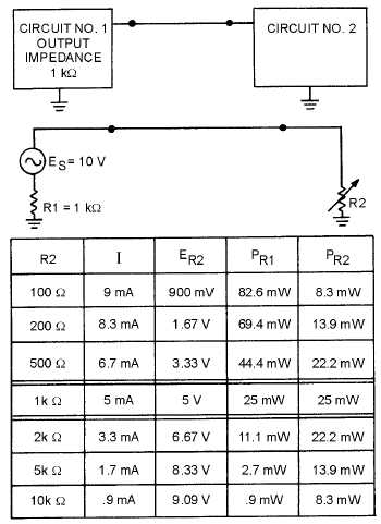
Figure 1-13 shows two circuits connected together. Circuit number 1 can be considered as an a.c.
source (ES) whose output impedance is represented by a resistor (R1). It can be considered as an a.c.
source because the output signal is an a.c. voltage and comes from circuit number 1 through the output
impedance. The input impedance of circuit number 2 is represented by a resistor in series with the source.
The resistance is shown as variable to show what will happen as the input impedance of circuit number 2
is changed.
Figure 1-13.—Effect of impedance matching in the coupling of two circuits.
The chart below the circuit shows the effect of a change in the input impedance of circuit number 2
(R2) on current (I), signal voltage developed at the input of circuit number 2 (ER2), the power at the output
of circuit number 1 (PR1), and the power at the input to circuit number 2 (PR2).
Two important facts are brought out in this chart. First, the power at the input to circuit number 2 is
greatest when the impedances are equal (matched). The power is also equal at the output of circuit
number 1 and the input of circuit number 2 when the impedance is matched. The second fact is that the
largest voltage signal is developed at the input to circuit number 2 when its input impedance is much
larger than the output impedance of circuit number 1. However, the power at the input of circuit number 2


