15
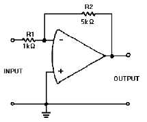
Figure 2D.—Inverting Configuration.
IN ANSWERING QUESTIONS 2-32
THROUGH 2-36, REFER TO FIGURE 2D.
2-32. In the inverting configuration of an
operational-amplifier circuit where are
the (a) input signal and (b) feedback
signal applied?
1. (a) Inverting input
(b) Inverting input
2. (a) Inverting input
(b) Noninverting input
3. (a) Noninverting input
(b) Inverting input
4. (a) Noninverting input
(b) Noninverting input
2-33. In the inverting configuration of an
operational-amplifier circuit with
feedback applied and a 1-volt, peak-to-
peak, sine wave as an input signal, what
is the amplitude of the signal at the
inverting input of the operational
amplifier?
1.
1 volt
2.
2 volts
3. 10 volts
4.
0 volts
2-34. In the inverting configuration of an
operational-amplifier circuit, when the
noninverting input of the operational
amplifier is grounded, what is the term
that describes the potential at the
inverting input of the operational
amplifier?
1. Feedback-signal voltage
2. Input-signal voltage
3. Signal ground
4. Virtual ground
2-35. If the amplitude of the input signal to the
circuit is +2 millivolts, what will the
amplitude of the output signal be?
1. -10 mV
2. -2 mV
3. +10 mv
4. +2 mV
2-36. If the unity gain point of the operational
amplifier is 1 mega-hertz, what is the
bandwidth of the circuit?
1. 100 kHz
2. 200 kHz
3. 300 kHz
4. 400 kHz
THIS SPACE LEFT BLANK
INTENTIONALLY.


