4-54
takes nothing for granted. You must prove to yourself that the equipment is operating properly and that no
other troubles exist.
If you find none of the defects listed under the visual check, go ahead with the signal tracing
procedure. The trouble is probably of such a nature that it cannot be seen directly-it may only be seen
using an oscilloscope.
Tracing the ac signal through the equipment is the most rapid and accurate method of locating a
trouble that cannot be found by a visual check, and it also serves as check on any repairs you may have
made. The idea is to trace the ac voltage from the transformer, to see it change to pulsating dc at the
rectifier output, and then see the pulsations smoothed out by the filter. The point where the signal stops or
becomes distorted is the place look for the trouble. If you have no dc output voltage, you should look for
an open or a short in your signal tracing. If you have a low dc voltage, you should look for a defective
part and keep your eyes open for the place where the signal becomes distorted.
Signal tracing is one method used to localize trouble in a circuit. This is done by observing the
waveform at the input and output of each part of a circuit.
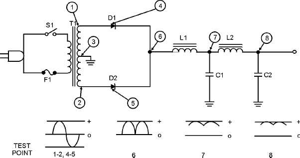
Let's review what each part of a good power supply does to a signal, as shown in figure 4-51. The ac
voltage is brought in from the power line by means of the line cord. This voltage is connected to the
primary of the transformer through the ON-OFF switch (S1). At the secondary winding of the transformer
(points 1 and 2), the scope shows you a picture of the stepped-up voltage developed across each half of
the secondary winding-the picture is that of a complete sine wave. Each of the two stepped-up voltages is
connected between ground and one of the two anodes of the rectifier diodes. At the two rectifier anodes
(points 4 and 5), there is still no change in the shape of the stepped-up voltage-the scope picture still
shows a complete sine wave.
Figure 4-51.—Complete power supply (without regulator).
However, when you look at the scope pattern for point 6 (the voltage at the rectifier cathodes), you
see the waveshape for pulsating direct current. This pulsating dc is fed through the first choke (L1) and
filter capacitor (C1) which remove a large part of the ripple, or "hum," as shown by the waveform for
point 7. Finally the dc voltage is fed through the second choke (L2) and filter capacitor (C2), which


