1-25
practical purposes, there is no output developed across the load resistor during the negative alternation of
the input signal as indicated by the broken lines in the figure. Although only one cycle of input is shown,
it should be realized that the action described above continually repeats itself, as long as there is an input.
Therefore, since only the positive half-cycles appear at the output this circuit converted the ac input into a
positive pulsating dc voltage. The frequency of the output voltage is equal to the frequency of the applied
ac signal since there is one pulse out for each cycle of the ac input. For example, if the input frequency is
60 hertz (60 cycles per second), the output frequency is 60 pulses per second (pps).
However, if the diode is reversed as shown in view B of figure 1-21, a negative output voltage would
be obtained. This is because the current would be flowing from the top of RL toward the bottom, making
the output at the top of RL negative with respect to the bottom or ground. Because current flows in this
circuit only during half of the input cycle, it is called a half-wave rectifier.
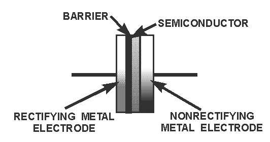
The semiconductor diode shown in the figure can be replaced by a metallic rectifier and still achieve
the same results. The metallic rectifier, sometimes referred to as a dry-disc rectifier, is a metal-to-
semiconductor, large-area contact device. Its construction is distinctive; a semiconductor is sandwiched
between two metal plates, or electrodes, as shown in figure 1-22. Note in the figure that a barrier, with a
resistance many times greater than that of the semiconductor material, is constructed on one of the metal
electrodes. The contact having the barrier is a rectifying contact; the other contact is nonrectifying.
Metallic rectifiers act just like the diodes previously discussed in that they permit current to flow more
readily in one direction than the other. However, the metallic rectifier is fairly large compared to the
crystal diode as can be seen in figure 1-23. The reason for this is: metallic rectifier units are stacked (to
prevent inverse voltage breakdown), have large area plates (to handle high currents), and usually have
cooling fins (to prevent overheating).
Figure 1-22.—A metallic rectifier.


