1-24
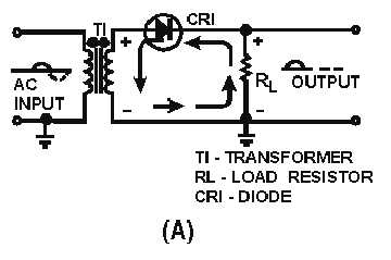
Figure 1-21A.—Simple half-wave rectifier.
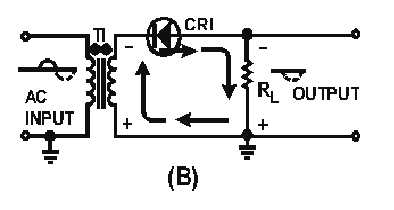
Figure 1-21B.—Simple half-wave rectifier.
The transformer (T1) in the figure provides the ac input to the circuit; the diode (CR1) provides the
rectification; and the load resistor (RL) serves two purposes: it limits the amount of current flow in the
circuit to a safe level, and it also develops the output signal because of the current flow through it.
Before describing how this circuit operates, the definition of the word "load" as it applies to power
supplies must be understood. Load is defined as any device that draws current. A device that draws little
current is considered a light load, whereas a device that draws a large amount of current is a heavy load.
Remember that when we speak of "load," we are speaking about the device that draws current from the
power source. This device may be a simple resistor, or one or more complicated electronic circuits.
During the positive half-cycle of the input signal (solid line) in figure 1-21 view A, the top of the
transformer is positive with respect to ground. The dots on the transformer indicate points of the same
polarity. With this condition the diode is forward biased, the depletion region is narrow, the resistance of
the diode is low, and current flows through the circuit in the direction of the solid lines. When this current
flows through the load resistor, it develops a negative to positive voltage drop across it, which appears as
a positive voltage at the output terminal.
When the ac input goes in a negative direction (fig. 1-21 view A), the top of the transformer becomes
negative and the diode becomes reverse biased. With reverse bias applied to the diode, the depletion
region increases, the resistance of the diode is high, and minimum current flows through the diode. For all


