2-4
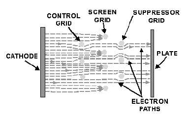
In this way, each grid will have maximum effect on the electron stream. There are two undesirable effects
associated with the staggered grid arrangement that make it unsuitable for use in power amplifiers.
Figure 2-4.—Electron flow in a conventional pentode.
First, no direct path exists between the cathode and the plate. Electrons leaving the cathode must run
an obstacle course around the grid wires to reach the plate. Some of these electrons are deflected by the
grid and scattered and, thus, never reach the plate. Second, some electrons strike the grid wires and are
removed from the electron stream as grid current. Because of these two undesirable effects, the amount of
plate current that can flow through the tube is greatly reduced. Because of this loss of electrons from the
stream, conventional tetrodes and pentodes are not suitable for power amplifiers. Therefore, a special
class of tubes has been developed to overcome this problem—the BEAM POWER TUBES and
POWER PENTODE TUBES.
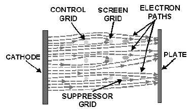
Figure 2-5 shows the cross section of the power pentode. Notice that there is no staggered grid
arrangement. Instead, each grid wire is directly in line with the grid in front of and behind it. The screen
and suppressor grids are shielded from the electron stream by the control grid. Because the screen grid is
"shielded" by the control grid, it can draw little grid current from the electron stream.
Figure 2-5.—Electron flow in a power pentode.
This arrangement of grids offers few obstacles to electron flow. Electrons will flow in "sheets"
between the grid wires to the plate. The effect is to allow more of the electrons leaving the cathode to


