4-5
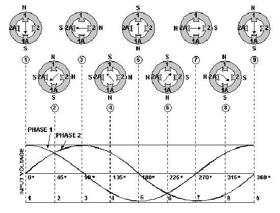
Figure 4-3.—Two-phase rotating field.
The waveforms in figure 4-3 are of the two input phases, displaced 90º because of the way they
were generated in a two-phase alternator. The waveforms are numbered to match their associated phase.
Although not shown in this figure, the windings for the poles 1-1A and 2-2A would be as shown in the
previous figure. At position 1, the current flow and magnetic field in winding 1-1A is at maximum
(because the phase voltage is maximum). The current flow and magnetic field in winding 2-2A is zero
(because the phase voltage is zero). The resultant magnetic field is therefore in the direction of the 1-1A
axis. At the 45-degree point (position 2), the resultant magnetic field lies midway between windings 1-1A
and 2-2A. The coil currents and magnetic fields are equal in strength. At 90º (position 3), the magnetic
field in winding 1-1A is zero. The magnetic field in winding 2-2A is at maximum. Now the resultant
magnetic field lies along the axis of the 2-2A winding as shown. The resultant magnetic field has rotated
clockwise through 90º to get from position 1 to position 3. When the two-phase voltages have completed
one full cycle (position 9), the resultant magnetic field has rotated through 360º . Thus, by placing two
windings at right angles to each other and exciting these windings with voltages 90º out of phase, a
rotating magnetic field results.
Two-phase motors are rarely used except in special-purpose equipment. They are discussed here to
aid in understanding rotating fields. You will, however, encounter many single-phase and three-phase
motors.
Q5.
What is the angular displacement between field poles in a two-phase motor stator?


