1-33
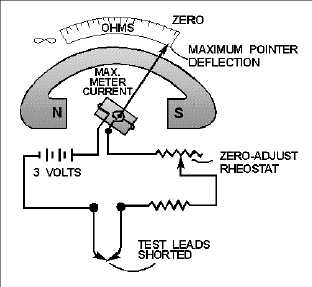
scale. Because of this current through the meter with the leads shorted, it is necessary to remove the test
leads when you are finished using the ohmmeter. If the leads were left connected, they could come in
contact with each other and discharge the ohmmeter battery. When the variable resistor (rheostat) is
adjusted properly, with the leads shorted, the pointer of the meter will come to rest exactly on the zero
position. This indicates ZERO RESISTANCE between the test leads, which, in fact, are shorted
together. The zero reading of a series-type ohmmeter is on the right-hand side of the scale, where as the
zero reading for an ammeter or a voltmeter is generally to the left-hand side of the scale. (There is another
type of ohmmeter which is discussed a little later on in this chapter.) When the test leads of an ohmmeter
are separated, the pointer of the meter will return to the left side of the scale. The interruption of current
and the spring tension act on the movable coil assembly, moving the pointer to the left side () of the
scale.
Figure 1-31.—A simple ohmmeter circuit.
USING THE OHMMETER
After the ohmmeter is adjusted for zero reading, it is ready to be connected in a circuit to measure
resistance. A typical circuit and ohmmeter arrangement is shown in figure 1-32.


