1-34
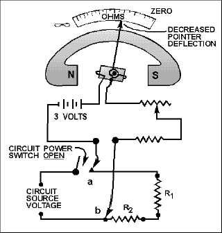
Figure 1-32.—Measuring circuit resistance with an ohmmeter.
The power switch of the circuit to be measured should always be in the OFF position. This prevents
the source voltage of the circuit from being applied across the meter, which could cause damage to the
meter movement.
The test leads of the ohmmeter are connected in series with the circuit to be measured (fig. 1-32).
This causes the current produced by the 3-volt battery of the meter to flow through the circuit being
tested. Assume that the meter test leads are connected at points a and b of figure 1-32. The amount of
current that flows through the meter coil will depend on the total resistance of resistors R1 and R2, and the
resistance of the meter. Since the meter has been preadjusted (zeroed), the amount of coil movement now
depends solely on the resistance of R1and R2. The inclusion of R1 and R2 raises the total series resistance,
decreasing the current, and thus decreasing the pointer deflection. The pointer will now come to rest at a
scale figure indicating the combined resistance of R1 and R2. If R1 or R2, or both, were replaced with a
resistor(s) having a larger value, the current flow in the moving coil of the meter would be decreased
further. The deflection would also be further decreased, and the scale indication would read a still higher
circuit resistance. Movement of the moving coil is proportional to the amount of current flow.
OHMMETER RANGES
The amount of circuit resistance to be measured may vary over a wide range. In some cases it may
be only a few ohms, and in others it may be as great as 1,000,000 ohms (1 megohm). To enable the meter
to indicate any value being measured, with the least error, scale multiplication features are used in most
ohmmeters. For example, a typical meter will have four test lead jacks-COMMON, R 1, R 10, and
R 100. The jack marked COMMON is connected internally through the battery to one side of the
moving coil of the ohmmeter. The jacks marked R 1, R 10, and R 100 are connected to three
different size resistors located within the ohmmeter. This is shown in figure 1-33.


