3-6
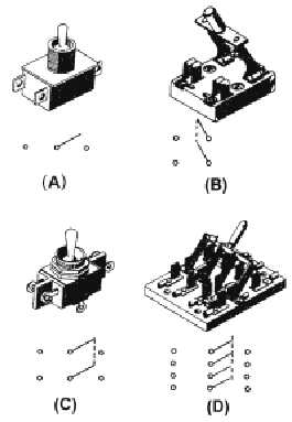
Figure 3-3.—Multicontact switches.
Figure 3-3(A) shows a single-pole, double-throw switch. The illustration shows three terminals
(connections) on this switch. The schematic symbol for the switch is also shown.
The center connection of the schematic symbol represents the point at which current enters the
switch. The left and right connections represent the two different points to which this current can be
switched. From the schematic symbol, it is easy to determine that this is a single-pole, double-throw
switch.
Now look at figure 3-3(B). The switch is shown with its schematic symbol. The schematic symbol
has two points at which current can enter the switch, so this is a double-pole switch. Each of the poles is
mechanically connected (still electrically separate) to one point, so this is a single-throw switch. Only one
throw is required to route two separate circuit paths through the switch.
Figure 3-3(C) shows a double-pole, double-throw switch and its schematic symbol. Figure 3-3(D)
shows a four-pole, double-throw switch and its schematic symbol.
It might help you to think of switches with more than one pole as several switches connected
together mechanically. For example, the knife switch shown in figure 3-3(D) could be thought of as four
single-pole, double-throw switches mechanically connected together.
Q4. What is the difference between a manual and an automatic switch?
Q5. What is one example of a manual switch?
Q6. What is one example of an automatic switch?
Q7. Why are multicontact switches used?


