3-16
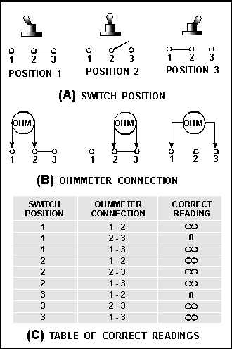
Figure 3-15.—Table of correct readings.
With the switch in position 1 and the ohmmeter connected to terminals 1 and 2 of the switch, the
ohmmeter should indicate (). When the ohmmeter is moved to terminals 2 and 3, the ohmmeter should
indicate zero ohms. With the ohmmeter connected to terminals 1 and 3, the indication should be ().
As you remember from chapter 1, before the ohmmeter is used, power must be removed from the
circuit and the component being checked should be isolated from the circuit. The best way to isolate the
switch is to remove it from the circuit completely. This is not always practical, and it is sometimes
necessary to check a switch while there is power applied to it. In these cases, you would not be able to use
an ohmmeter to check the switch, but you can check the switch by the use of a voltmeter.
Figure 3-16(A) shows a switch connected between a power source (battery) and two loads. In figure
3-16(B), a voltmeter is shown connected between ground and each of the three switch terminals while the
switch is in position 1. Figure 3-16(C) is a table showing the switch position, voltmeter connection, and
the correct voltmeter reading.


