1-21
MAXWELL BRIDGE
The Maxwell bridge, shown in view C of figure 1-14, measures inductance by comparing it with a
capacitance and (effectively) two resistances.] This bridge circuit is employed for measuring inductances
having losses greater than 0.05 (expressed by the D dial reading). For such inductors it is necessary to
introduce, in place of the series control (D dial), a new loss control (Q dial), which shunts the standard
capacitor. This control, which becomes effective when the FUNCTION switch is turned to the L(Q)
position, is conveniently calibrated in values of Q, the storage factor of the inductor under measurement.
The balance for inductance is the same for either bridge circuit. This permits the use of the same markings
on the RANGE switch for both the L(D) and L(Q) positions of the FUNCTION switch.
REACTANCE MEASURING EQUIPMENT
The reactance type of inductance measuring equipment makes use of the following principle: If an ac
voltage of fixed frequency is applied across an inductor (and a resistor in series), the voltage drop
produced across the reactance of the inductor by the resulting current flow is directly proportional to the
value of the inductance. An inductance measurement using the reactance method is identical to
capacitance measurements using the same method, except that current flow is directly proportional to the
value of inductance, rather than inversely proportional as in the case of capacitance. It follows then that if
a reactance-type capacitance measuring equipment is provided with a chart that converts the capacitance
readings to equivalent inductance values and a proper range multiplying factor, the same test setup can be
used to measure both capacitance and inductance. In practice, test equipment using the reactance method
for capacitance measurements usually provides an inductance conversion chart. Because the current
flowing through the inductance under test is directly proportional to the value of inductance, the
reciprocals of the capacitance range multipliers must be used; for example, a multiplier of 0.1 becomes
and a multiplier of 100 becomes
The reactance-type equipment gives approximate values only. Like the analog multimeter, it is used
only when portability and speed are more important than precision. If the ohmic resistance of the inductor
is low, the inductance value obtained from the conversion chart can be used directly. If the ohmic value
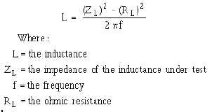
(as measured with an ohmmeter) is appreciable, a more accurate value of inductance can be obtained by
use of the following formula:


