1-18
course is made up of both the reactance and the resistance. Therefore, the capacitance indicated by the
analyzer will be lower than the actual value.
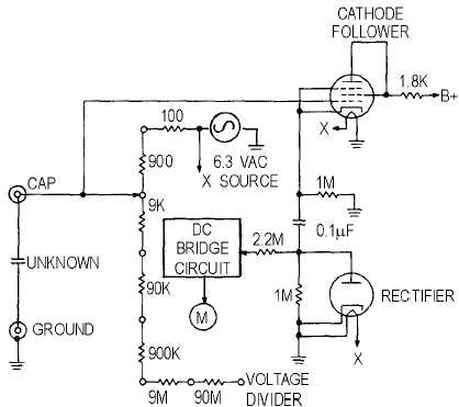
Figure 1-13 shows a simplified schematic diagram of the capacitance-measuring section of a typical
reactance-type electronic volt-ohm-capacitance milliammeter. A 6.3-vac voltage is taken from the
filament source and applied across the resistive voltage divider network to determine the designated value
of the capacitor. Because of a particular use or circuit application, some capacitors are permitted an even
wider variation of capacitance value than is indicated by their rated tolerances.
Figure 1-13.—Reactance-type capacitance meter.
INDUCTANCE MEASUREMENT
A current flowing through a conductor produces a magnetic field around that conductor. If the
conductor is formed into a coil, a stronger magnetic field is set up. The relationship between the strength
of the field and the intensity of the current causing it is expressed by the inductance of the coil (or
conductor). When the current producing the magnetic field ceases, the energy of the magnetic field is
returned in part to the circuit source in the form of a reverse current. Inductance, then, is the ability of a
coil to function as a storehouse of energy in magnetic form and is determined by the shape and
dimensions of the coil. Inductance is measured in henries, millihenries, or microhenries. Inductors can be
described generally as circuit elements used to introduce inductive reactance into ac circuits.
An inductor is essentially a coil of wire wound around a form using a core of air, magnetic metal, or
nonmagnetic metal. A core of magnetic metal produces greater inductance (for a coil of given size and
number of turns) than does an air core; a core of nonmagnetic metal produces less inductance than does
an air core. At frequencies in the hf and higher regions of the frequency spectrum, coils of small size and


