2-11
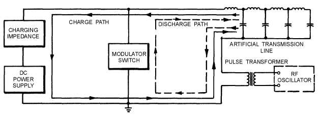
Figure 2-6.—Modulator with an artificial transmission line for the storage element.
The charge path includes the primary of the pulse transformer, the dc power supply, and the charging
impedance. When the modulator switch is closed, the transmission line discharges through the series
circuit. This circuit consists of the modulator switch and the primary of the pulse transformer.
The artificial transmission line is effectively an open circuit at its output end. Therefore, when the
voltage wave reaches the output end of the line, it is reflected. As the reflected wave propagates from the
output end back toward the input end of the line, it completely discharges each section of the line. When
the reflected wave reaches the input end of the line, the line is completely discharged, and the modulator
pulse ceases abruptly. If the oscillator and pulse transformer circuit impedance is properly matched to the
line impedance, the voltage pulse that appears across the transformer primary equals one-half the voltage
to which the line was initially charged.
The width of the pulse generated by an artificial transmission line depends on the time required for a
voltage wave to travel from the input end to the output end of the line and back. Therefore, we can say the
pulse width depends on the velocity of propagation along the line (determined by the inductances and
capacitances of each section of the line) and the number of line sections (the length of the line).
PULSE-FORMING NETWORKS.—A pulse-forming network is similar to an artificial
transmission line in that it stores energy between pulses and produces a nearly rectangular pulse. The
pulse-forming network in view B of figure 2-5 consists of inductors and capacitors so arranged that they
approximate the behavior of an artificial transmission line.
Each capacitor in the artificial transmission line, shown in view A, must carry the high voltage
required for the modulator pulse. Because each capacitor must be insulated for this high voltage, an
artificial transmission line consisting of many sections would be bulky and cumbersome.
The pulse-forming network, shown in view B of figure 2-5, can carry high voltage but does not
require bulky insulation on all of its capacitors. Only series capacitor C1 must have high-voltage
insulation. Because the other capacitors are in parallel with the corresponding inductors, the modulator-
pulse voltage divides nearly equally among them. Thus, except for C1, the elements of the pulse-forming
network are relatively small.
Pulse-forming networks are often insulated by immersing each circuit element in oil. The network is
usually enclosed in a metal box on which the pulse width, characteristic impedance, and safe operating
voltage of the network are marked. If one element in such a network fails, the entire network must be
replaced.