2-10
transmitted rf pulses) and (2) to discharge and form a rectangular dc pulse (modulator pulse) of the
required duration when the modulator switch is closed.
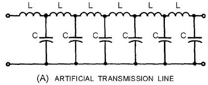
Figure 2-5A.—Modulator storage elements.
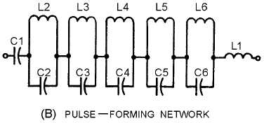
Figure 2-5B.—Modulator storage elements.
The duration of the modulator pulse depends on the values of inductance and capacitance in each LC
section of the artificial transmission line in view A and the number of LC sections used. Other
arrangements of capacitors and inductors (such as the pulse-forming network shown in view B) are very
similar in operation to artificial transmission lines.
ARTIFICIAL TRANSMISSION LINES and PULSE-FORMING NETWORKS (pfn) are used more
often than the capacitor-type storage elements.
ARTIFICIAL TRANSMISSION LINE.—Figure 2-6 shows a radar modulator that uses an
artificial transmission line as its storage element. A modulator switch controls the pulse-repetition rate.
When the modulator switch is open (between transmitted rf pulses), the transmission line charges.