6-24
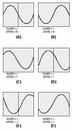
Figure 6-27.—Effects of SLOPE and TRIGGER LEVEL controls.
In most scopes, an automatic function of the trigger circuitry allows a free-running trace without a
trigger signal. However, when a trigger signal is applied, the circuit reverts to the triggered mode of
operation and the sweep is no longer free running. This action provides a trace when no signal is applied.
Synchronization is also used to cause a free-running condition without a trigger signal.
Synchronization is not the same as triggering. TRIGGERING refers to a specific action or event that
initiates an operation. Without this event, the operation would not occur. In the case of the triggered
sweep, the sweep will not be started until a trigger is applied. Each succeeding sweep must have a trigger
before a sweep commences. SYNCHRONIZATION, however, means that an operation or event is
brought into step with a second operation.
A sweep circuit that uses synchronization instead of triggering will cause a previously free-running
sweep to be locked in step with the synchronizing signal. The TRIGGER LEVEL control setting can be
increased until synchronization occurs; but, until that time, an unstable pattern will appear on the CRT
face.
COUPLING Section
The COUPLING section allows you to select from four positions: AC, LF REJ, HF REJ, and DC.
The AC position incorporates a coupling capacitor to block any dc component. The LF and HF REJ
positions reject low- and high-frequency components, respectively. The DC position provides direct