6-22
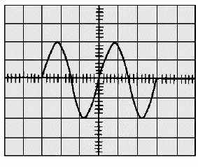
Figure 6-25.—Time measurement of a waveform (TIME/DIV).
In selecting a time base, you should select one that is lower in frequency than the input signal. If the
input signal requires 5 milliseconds to complete one cycle and the sawtooth is set for 0.5 milliseconds per
centimeter with a 10-centimeter-wide graticule, then approximately one cycle will be displayed. If the
time base is set for 1 millisecond per centimeter, approximately two cycles will be displayed. If the time
base is set at a frequency higher than the input frequency, only a portion of the input signal will be
displayed.
In the basic oscilloscope, the sweep generator runs continuously (FREE-RUNNING); in more
elaborate oscilloscopes, it is normally turned off. In the oscilloscope we’re using as an example, the sweep
generator can be triggered by the input signal or by a signal from some other source. (Triggering will be
discussed later in this chapter.) This type of oscilloscope is called a triggered oscilloscope. The triggered
oscilloscope permits more accurate time measurements to be made and provides a more stable
presentation than the nontriggered-type oscilloscope.
On some oscilloscopes, you will find a 10 times (10X) magnification control. As previously
mentioned, this allows the displayed sweep to be magnified by a factor of 10.
Q-15. When you select the time base to display a signal, should the time base be the same, higher, or
lower than the input signal?
COMPONENTS USED TO PROVIDE A STABLE DISPLAY
The triggering and level controls are used to synchronize the sweep generator with the input signal.
This provides a stationary waveform display. If the input signal and horizontal sweep generator are
unsynchronized, the pattern tends to jitter, making observations difficult.
The A TRIGGER controls at the lower right of the scope (figure 6-26) are used to control the
stability of the oscilloscope CRT display. They are provided to permit you to select the source, polarity,
and amplitude of the trigger signal. These controls, labeled A TRIGGER, LEVEL, SOURCE, and
SLOPE, are described in the following paragraphs.