6-23
Figure 6-26.—Components that control stability.
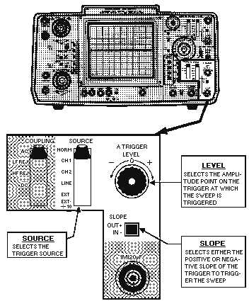
SOURCE Control
The SOURCE control allows you to select the appropriate source of triggering. You can select input
signals from channel 1 or 2, the line (60 hertz), or an external input.
TRIGGER LEVEL/SLOPE Controls
The LEVEL control allows you to select the amplitude point of the trigger signal at which the sweep
is triggered. The SLOPE lets you select the negative or positive slope of the trigger signal at which the
sweep is triggered.
The TRIGGER LEVEL (mounted with the TRIGGER SLOPE on some scopes) determines the
voltage level required to trigger the sweep. For example, in the TRIGGER modes, the trigger is obtained
from the signal to be displayed. The setting of the LEVEL control determines the amplitude point of the
input waveform that will be displayed at the start of the sweep.
Figure 6-27 shows some of the displays for a channel that can be obtained for different TRIGGER
LEVEL and TRIGGER SLOPE settings. The level is zero and the slope is positive in view A; view B also
shows a zero level but a negative slope selection. View C shows the effects of a positive trigger level
setting and positive trigger slope setting; view D displays a negative trigger level setting with a positive
trigger slope setting. Views E and F have negative slope settings. The difference is that view E has a
positive trigger level setting, whereas F has a negative trigger level setting.