4-13
Table 4-1.—Basic Measurement Instructions
MEASUREMENT
FUNCTION
RANGE
INPUT
CONNECTION
MAXIMUM
OVERLOAD
REMARKS
DC Volts
DCV
200MV, 2,
20, 200, or
1200V
V Ÿ DQG
COMMON
1200V dc or 1200V
rms (sinusoidal)
Auto-polarity
DC Milliamperes
DC MA
$
200, or
2000MA
MA and
COMMON
2A (fuse protected)
AC Volts
ACV
200MV, 2,
20, 200, or
1200V
V Ÿ DQG
COMMON
1200V rms
(sinusoidal), not to
exceed 107 V-Hz on
20, 200, 1200V
ranges. 500V rms
(sinusoidal) on
200mV and 2V
ranges.
AC Milliamperes
AC MA
$
200, or
2000MA
MA and
COMMON
2A (fuse protected)
Kilohms
KŸ
200, or
.
V Ÿ DQG
COMMON
130V rms, 200ŸDQG
2KŸ UDQJHV 9
rms, 20kŸ WKUX
2000kŸ UDQJHV
Megohms
0
Any
V Ÿ DQG
COMMON
250V rms
Ranges switches
non-functional
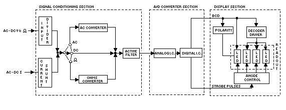
Block Diagram Analysis
Figure 4-9 is a block diagram of an electronic digital multimeter. Note that the block diagram divides
the instrument into three major sections: the SIGNAL CONDITIONING section, the ANALOG-TO-
DIGITAL CONVERTER section, and the DISPLAY section.
Figure 4-9.—Model 8000A block diagram.