4-12
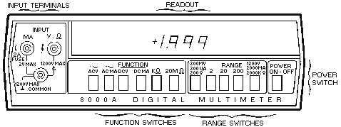
Figure 4-8.—Digital voltmeter 8000A operating features.
Operating Features
The locations of all controls, connectors, and indicators are shown in figure 4-8. The INPUT
terminals, located on the left-hand side of the meter face, provide input connections for voltage or
resistance (V-?) and milliampere current (MA) measurements with respect to the common terminal. The
readout section, located across the upper half of the meter face, contains light-emitting diode (LED)
indicators. They display the measured input and polarity signs for dc measurements. The POWER switch,
located on the lower right-hand side of the meter face, is a push-button switch used to energize the
instrument. The RANGE switches, located on the lower, middle, right-hand portion of the meter face,
select the voltage (200 millivolts, 2, 20, 200, or 1,200 volts), current (200 microamperes, 2, 200, or 2,000
milliamperes), and resistance (200 ohms, 2, 20, 200, or 2,000 kilohms) ranges. The FUNCTION switches,
located on the lower, middle, left-hand portion of the meter face, select the voltage, current, or resistance
modes. The MA input terminal is also a fuse holder for the current protection fuse.
Internal Battery Models
Power is supplied by internal rechargeable batteries that allow the instrument to operate for at least 8
hours. Recharging the batteries is accomplished by switching the POWER switch to OFF and connecting
the instrument to an ac power line. You can use the instrument when recharging the batteries on ac power,
but the recharging time will be extended.
Q-5. Power for the electronic digital multimeter is normally supplied by what internal power source?
Overload Protection
An overload condition is indicated by the simultaneous flashing of the display readouts. The dc
voltage function can withstand up to 1,200 volts dc or 1,200 volts root-mean-square (rms) on any range.
Q-6. How is an overload condition indicated by the electronic digital multimeter?
The ac voltage function can sustain up to 1,200 volts rms on the 20-, 200-, and 1,200-volt ranges and
500 volts rms on the 200-millivolt and 2-volt ranges. The current input fuse is protected above 2 amperes
rms. Protection for the resistance function is to 130 volts rms in the 200-ohm and 2-kilohm ranges, and
250 volts rms in the 20-kilohm through 20-megohm ranges.
Basic Digital Multimeter Measurement
Table 4-1 lists the proper function push buttons, range push buttons, and input terminal connections
for performing specific measurements with the model 8000A.