1-55
Trouble in a synchro system that has been in operation for some time is usually one of two types.
First, the interconnecting synchro wiring often passes through a number of switches; at these points
opens, shorts, or grounds may occur. You will be expected to trace down these troubles with an
ohmmeter. You can find an open easily by checking for continuity between two points. Similarly, you can
find a ground by checking the resistance between the suspected point and ground. A reading of zero ohms
means that the point in question is grounded. Secondly, the synchro itself may become defective, due to
opens and shorts in the windings, bad bearings, worn slip rings, or dirty brushes. You can do nothing
about these defects except replace the synchro.
Troubles in new and modified synchro systems are most often because of (1) improper wiring and
(2) misalignment caused by synchros not being zeroed. You are responsible for finding and correcting
these troubles. You can check for improper wiring with an ohmmeter by making a point-to-point
continuity and resistance check. You can correct misalignment of a synchro system by rezeroing the
entire system.
TROUBLE INDICATORS
When trouble occurs in an electronic installation that contains a large number of synchro systems, it
may be very difficult to isolate the trouble to one particular system. Since it is vital that maintenance
personnel locate the point of trouble and fix it in as short a time as possible, indicators, which aid in
locating the trouble quickly, are included in the equipment. These indicators are usually signal lights,
mounted on a central control board and connected to the different synchro systems. When trouble occurs
in a synchro system, the signal light connected to it may either light or flash. Maintenance personnel
identify the defective system by reading the name or number adjacent to the light.
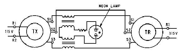
Signal lights indicate either overload conditions or blown fuses. Overload indicators are usually
placed in the stator circuit of a torque synchro system because the stator circuit gives a better indication of
mechanical loading than does the current in the rotor circuit. One version of this type of indicator, as
shown in figure 1-44, consists of a neon lamp connected across the stator leads of a synchro system by
two transformers. The primaries, consisting of a few turns of heavy wire, are in series with two of the
stator leads; the secondaries, consisting of many turns of fine wire, are in series with the lamp. The turns
ratios are designed so that when excess current flows through the stator windings, the neon lamp lights.
For example, when the difference in rotor positions exceeds about 18º, the lamp lights, indicating that the
load on the motor shaft is excessive.
Figure 1-44.—Overload stator current indicator.
Blown fuse indicators are front panel lights which light when a protective fuse in series with the
rotor blows. Figure 1-45 shows a typical blown fuse indicator. If excessive current flows in the rotor
windings of this circuit because of a short or severe mechanical overload, one of the fuses will blow and
the neon lamp across the fuse will light.