1-22
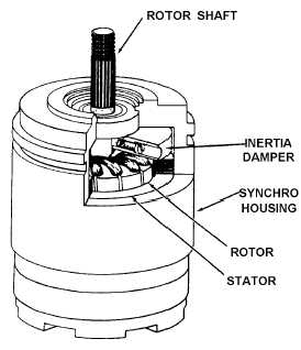
Figure 1-15.—Cutaway view of torque receiver with inertia damper.
Q-22. What is the physical difference between a synchro transmitter and a synchro receiver?
Q-23. What method is used to prevent oscillations in large synchro units?
TORQUE SYNCHRO SYSTEM
A torque transmitter (TX) and a torque receiver (TR) make up a simple torque-synchro system.
Basically, the electrical construction of synchro transmitters and receivers is similar, but their intended
functions are different. The rotor of a synchro transmitter is usually geared to a manual or mechanical
input. This gearing may drive a visual indicator showing the value or quantity being transmitted. The
rotor of the receiver synchronizes itself electrically with the position of the rotor of the transmitter and
thus responds to the quantity being transmitted.
BASIC SYNCHRO SYSTEM OPERATION
A simple synchro transmission system consisting of a torque transmitter connected to a torque
receiver (TX-TR) is illustrated in figure 1-16. As you can see, in this system the rotors are connected in
parallel across the ac line. The stators of both synchros have their leads connected S1 to S1, S2 to S2, and
S3 to S3, so the voltage in each of the transmitter stator coils opposes the voltage in the corresponding
coils of the receiver. The voltage directions are indicated by arrows for the instant of time shown by the
dot on the ac line voltage.

