1-49
jumper between these terminals at the TR should not affect the circuit. If, however, the TR rotor moves
when you connect a jumper, there is a slight voltage difference between S1 and S3. This voltage
difference indicates that the transmitter is not on electrical zero. If this is the case, recheck the transmitter
for electrical zero.
Zeroing Differential Synchros (Voltmeter Method)
A differential synchro is zeroed when it can be inserted into a system without introducing any
change. If a differential synchro requires zeroing, use the following voltmeter method:
1. Carefully and accurately set the unit whose position the CDX or TDX transmits on zero or on its
reference position. In the case of the TDR, deenergize the circuit and disconnect all leads before
setting its rotor to 0º or to its reference position. You may need to secure the rotor in this position;
taping the dial to the frame is usually sufficient.
2. Deenergize the circuit and disconnect all leads on the differential except leads S2 and S3 when
you use the 78-volt (10.2 volts for 26-volt units) supply from the transmitting unit to zero the
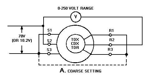
differential. Set the voltmeter to its 0- to 250-volt scale and connect it as shown in view A of
figure 1-39. If the 78-volts is not available from the transmitter or from an auto transformer, you
may use a 115-volt source instead. If you use 115 volts instead of 78 volts, do not leave the
synchro connected for more than 2 minutes or it will overheat and may become permanently
damaged.
Figure 1-39A.—Zeroing differential synchros by the voltmeter method.