1-47
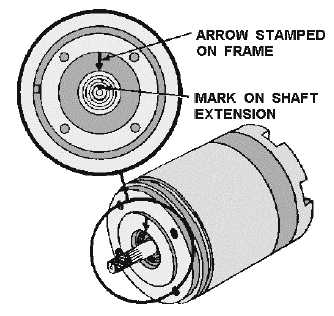
Figure 1-37.—Coarse electrical zero markings.
For the ac voltmeter method to be as accurate as possible, an electronic or precision voltmeter having
0- to 250-volt and a 0- to 5-volt ranges should be used. On the low scale this meter should also be able to
measure voltages as low as 0.1 volt.
Q-59. What is the reference point for alignment of all synchro units?
Q-60. What is the most accurate method of zeroing a synchro?
Q-61. What is the purpose of the coarse setting of a synchro?
Zeroing Transmitters and Receivers (Voltmeter Method)
Since the TX, CX, and TR are functionally and physically similar, they can be zeroed in the same
manner. For the TX and CX to be properly zeroed, electrical zero voltages (S2 = 52V; S1 and S3 = 26V)
must exist across the stator winding when the rotor of the transmitter is set to 0º or its mechanical
reference position. The synchro receiver (TR) is properly zeroed when the device it actuates assumes its
zero or mechanical reference position while electrical zero voltages (S2 = 52V; S1 and S3 = 26V) exist
across its stator windings. The following is a step-by-step procedure used to zero the TX, CX, and TR.
1. Carefully set the unit (antenna, gun mount, director, etc.) whose position the CX or TX transmits,
accurately on 0º or on its reference position. In the case of the TR, deenergize the circuit and
disconnect the stator leads before setting its rotor on zero or to its reference position. The rotor
may need to be secured in this position; taping the dial to the frame is usually sufficient.
2. Deenergize the synchro circuit and disconnect the stator leads. NOTE: Many synchro systems are
energized by individual switches. Therefore, be sure that the synchro power is off before working
on the connections.Set the voltmeter to its 0- to 250-volt scale and connect it into the circuit as
shown in view A of figure 1-38.