1-24
approaches correspondence, the stator voltages of the transmitter and receiver approach equality. This
action decreases the stator currents and produces a decreasing torque on the receiver. When the receiver
and the transmitter are again in correspondence, as shown in view C, the stator voltages between the two
synchros are equal and opposite (S1 = 52V; S2 and S3 = 26V), the rotor torque is zero, and the rotors are
displaced from zero by the same angle (60º). This sequence of events causes the transmitter and receiver
to stay in correspondence.
In the system we just explained, the receiver reproduced the signal from the transmitter. As you can
see, a synchro system such as this could provide a continuous, accurate, visual reproduction of important
information to remote locations.
Q-24. What two components make up a simple synchro transmission system?
Q-25. What leads in a simple synchro system are connected to the ac power line?
Q-26. What is the relationship between the transmitter and receiver stator voltages when their rotors
are in correspondence?
Q-27. What is the name given to the angle through which a transmitters rotor is mechanically rotated?
Receiver Rotation
When the teeth of two mechanical gears are meshed and a turning force is applied, the gears turn in
opposite directions. If a third gear is added, the original second gear turns in the same direction as the
first. This is an important concept, because the output of a synchro receiver is often connected to the
device it operates through a train of mechanical gears. Whether or not the direction of the force applied to
the device and the direction in which the receiver rotor turns are the same depends on whether the number
of gears in the train is odd or even. The important thing, of course, is to move the dial or other device in
the proper direction. Even when there are no gears involved, the receiver rotor may turn in the direction
opposite to the direction you desire. To correct this problem, some method must be used to reverse the
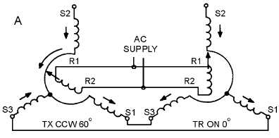
receiver's direction of rotation. In the transmitter-receiver system, this is done by reversing the S1 and S3
connections so that SI of the transmitter is connected to S3 of the receiver and vice versa (fig. 1-17), view
(A) and view (B).
Figure 1-17A.—Effect of reversing the S1 and S3 connections between the transmitter and the receiver.