2-10
THE OR GATE
The OR gate differs from the AND gate in that only ONE input has to be HIGH to produce a HIGH
output. An easy way to remember the OR gate is that any HIGH input will yield a HIGH output.
LOGIC SYMBOL
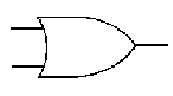
Figure 2-6shows the standard symbol for the OR gate. The number of inputs will vary according to
the needs of the designer.
Figure 2-6. —OR gate.
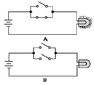
The OR gate may also be represented by a simple circuit as shown in figure 2-7. In the OR gate, two
switches are placed in parallel. If either or both of the switches are closed (view A), the lamp will light.
The only time the lamp will not be lit is when both switches are open (view B).
Figure 2-7. —OR gate equivalent circuit: A. Logic 1 state; B. Logic 0 state.
Let’s assume we are applying two variables, X and Y, to the inputs of an OR gate. For the circuit to
produce a HIGH output, either variable X, variable Y, or both must be HIGH. The Boolean expression for
this operation is f = X+Y and is spoken "f equals X OR Y." The plus sign indicates the OR function and
should not be confused with addition.
OR GATE OPERATION
Look at figure 2-8. At time T0, both X and Y are LOW and f is LOW. At T1, X goes HIGH
producing a HIGH output. At T2 when both inputs go LOW, f goes LOW. When Y goes HIGH at T3, f