2-7
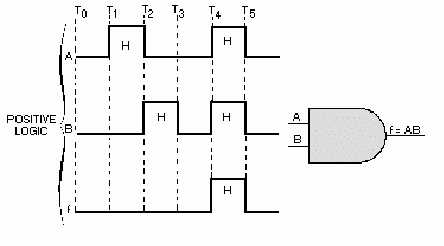
and B are HIGH. As a result, f is HIGH. The input requirements have been satisfied, so the output is
HIGH (logic 1).
Figure 2-4. —AND gate input and output signals.
TRUTH TABLE
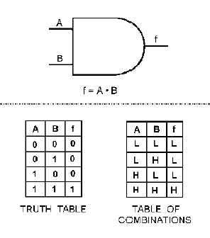
Now let’s refer to figure 2-5. As you can see, a Truth Table and a Table of Combinations are shown.
The latter is a deviation of the Truth Table. It uses the HIGH and LOW logic levels to depict the gate’s
inputs and resultant output combinations rather than the 1 and 0 logic states. By comparing the inputs and
outputs of the two tables, you see how one can easily be converted to the other (remember, 1 = HIGH and
0 = LOW). The Table of Combinations is shown here only to familiarize you with its existence, it will not
be seen again in this book. As we mentioned earlier, the Truth Table is a chart that shows all possible
combinations of inputs and the resulting outputs. Compare the AND gate Truth Table (figure 2-5) with
the input signals shown in figure 2-4.
Figure 2-5. —AND gate logic symbol, Truth Table, and Table of Combinations.


