2-5
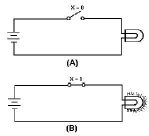
Figure 2-1. —Logic switch: A. Logic 0 state; B. Logic 1 state.
Closing the switch (view B), represents the logic 1 state of X. Closing the switch completes the
circuit causing the lamp to light. The 1 state of X satisfied the input requirement and the circuit therefore
produced the desired output (logic HIGH); current was applied to the lamp causing it to light.
If you consider the lamp as the output of a logic device, then the same conditions exist. The TRUE
(1 state) output of the logic device is to have the lamp lit. If the lamp is not lit, then the output of the logic
device is FALSE (0 state).
As you study logic circuits, it is important that you remember the state (1 or 0) of the inputs and
outputs.
So far in this chapter, we have discussed the two conditions of logical statements, the logic states
representing these two conditions, logic levels and associated electrical signals and positive and negative
logic. We are now ready to proceed with individual logic device operations. These make up the majority
of computer circuitry.
As each of the logic devices are presented, a chart called a TRUTH TABLE will be used to illustrate
all possible input and corresponding output combinations. Truth Tables are particularly helpful in
understanding a logic device and for showing the differences between devices.
The logic operations you will study in this chapter are the AND, OR, NOT, NAND, and NOR. The
devices that accomplish these operations are called logic gates, or more informally, gates. These gates are
the foundation for all digital equipment. They are the "decision-making" circuits of computers and other
types of digital equipment. By making decisions, we mean that certain conditions must exist to produce
the desired output.
In studying each gate, we will introduce various mathematical SYMBOLS known as BOOLEAN
ALGEBRA expressions. These expressions are nothing more than descriptions of the input requirements
necessary to activate the circuit and the resultant circuit output.


