2-4
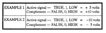
Table 2-3.—Examples of Negative Logic
NOTE: The logic level LOW now represents the 1 state. This is because the 1 state voltage is more
negative than the 0 state.
In the examples shown for negative logic, you notice that the voltage for the logic 1 state is more
negative with respect to the logic 0 state voltage. This holds true in example 1 where both voltages are
positive. In this case, it may be easier for you to think of the TRUE condition as being less positive than
the FALSE condition. Either way, the end result is negative logic.
The use of positive or negative logic for digital equipment is a choice to be made by design
engineers. The difficulty for the technician in this area is limited to understanding the type of logic being
used and keeping it in mind when troubleshooting.
NOTE:
UNLESS OTHERWISE NOTED, THE REMAINDER OF THIS BOOK WILL DEAL
ONLY WITH POSITIVE LOGIC.
LOGIC INPUTS AND OUTPUTS
As you study logic circuits, you will see a variety of symbols (variables) used to represent the inputs
and outputs. The purpose of these symbols is to let you know what inputs are required for the desired
output.
If the symbol A is shown as an input to a logic device, then the logic level that represents A must be
HIGH to activate the logic device. That is, it must satisfy the input requirements of the logic device
before the logic device will issue the TRUE output.
Look at view A of figure 2-1. The symbol X represents the input. As long as the switch is open, the
lamp is not lit. The open switch represents the logic 0 state of variable X.