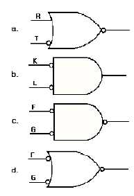
2-23
Q26. What is the output Boolean expression for the following gates?
LOGIC GATES IN COMBINATION
When you look at logic circuit diagrams for digital equipment, you are not going to see just a single
gate, but many combinations of gates. At first it may seem confusing and complex. If you interpret one
gate at a time, you can work your way through any network. In this section, we will analyze several
combinations of gates and then provide you with some practice problems.
Figure 2-23 (view A) shows a simple combination of AND gates. The outputs of gates 1 and 2 are
the inputs to gate 3. You already know that both inputs to an AND gate must be HIGH at the same time in
order to produce a HIGH output.

