1-20
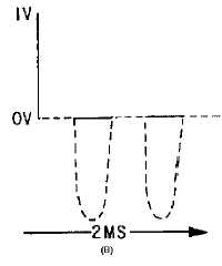
Figure 1-12B.—Waveform in a circuit with nonlinear impedances.
The waveform in view (B) is no longer identical to that of view (A) and the nonlinear impedance
network has generated HARMONIC FREQUENCIES. The waveform now consists of the fundamental
frequency and its harmonics. (Harmonics were discussed in NEETS, Module 9, Introduction to
Wave-Generation and Wave-Shaping Circuits.)
TWO SINE WAVE GENERATORS IN LINEAR CIRCUITS
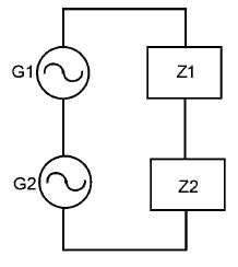
A circuit composed of two sine-wave generators, G1 and G2, and two linear impedances, Z1 and Z2,
is shown in figure 1-13. The voltage applied to Z1 and Z2 will be the vector sum of the generator
voltages. The sum of the individual instantaneous voltages across each impedance will equal the applied
voltages.
Figure 1-13.—Two sine-wave generators with linear impedances.
If the two generator outputs are of the same frequency, then the waveform across Z1 and Z2 will be a
sine wave, as shown in figure 1-14, views (A) and (B). No new frequencies will be created. Relative
amplitude and phase will be determined by the relative values and types of the impedances.


