3-6
The regenerative detector is used to receive short-wave code signals because it is easy to adjust and
has high sensitivity and good selectivity. At high frequencies, the amount of signal detuning necessary to
produce an audio-beat note is a small percentage of the signal frequency and causes no trouble. The use of
the regenerative detector for low-frequency code reception, however, is usually avoided. At low
frequencies the detuning required to produce the proper audio-beat frequency is a considerable percentage
of the signal frequency. Although this type detector may be used for AM signals, it has high distortion
and is not often used.
Q-7.
What simple, one-transistor detector circuit uses the heterodyne principle?
Q-8.
What three functions does the transistor in a regenerative detector serve?
AM DEMODULATION
Amplitude modulation refers to any method of modulating an electromagnetic carrier frequency by
varying its amplitude in accordance with the message intelligence that is to be transmitted. This is
accomplished by heterodyning the intelligence frequency with the carrier frequency. The vector
summation of the carrier, sum, and difference frequencies causes the modulation envelope to vary in
amplitude at the intelligence frequency, as discussed in chapter 1. In this section we will discuss several
circuits that can be used to recover this intelligence from the variations in the modulation envelope.
DIODE DETECTORS
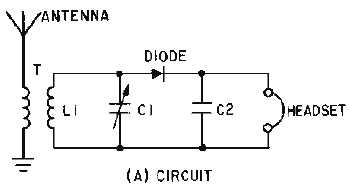
The detection of AM signals ordinarily is accomplished by means of a diode rectifier, which may be
either a vacuum tube or a semiconductor diode. The basic detector circuit is shown in its simplest form in
view (A) of figure 3-5. Views (B), (C), and (D) show the circuit waveforms. The demodulator must meet
three requirements: (1) It must be sensitive to the type of modulation applied at the input, (2) it must be
nonlinear, and (3) it must provide filtering. Remember that the AM waveform appears like the diagram of
view (B) and the amplitude variations of the peaks represent the original audio signal, but no modulating
signal frequencies exist in this waveform. The waveform contains only three rf frequencies: (1) the
carrier frequency, (2) the sum frequency, and (3) the difference frequency. The modulating intelligence is
contained in the difference between these frequencies. The vector addition of these frequencies provides
the modulation envelope which approximates the original modulating waveform. It is this modulation
envelope that the DIODE DETECTORS use to reproduce the original modulating frequencies.
Figure 3-5A.—Series-diode detector and wave shapes. CIRCUIT.

