1-26
Figure 1-34B.—Waveguide operation in other than dominant mode.
Circular waveguides are used in specific areas of radar and communications systems, such as
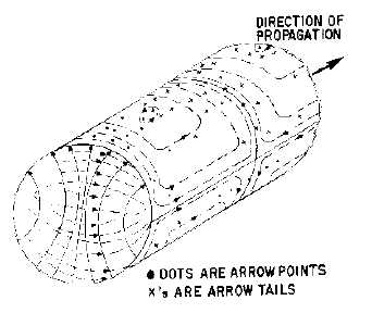
rotating joints used at the mechanical point where the antennas rotate. Figure 1-35 illustrates the dominant
mode of a circular waveguide. The cutoff wavelength of a circular guide is 1.71 times the diameter of the
waveguide. Since the "a" dimension of a rectangular waveguide is approximately one half-wavelength at
the cutoff frequency, the diameter of an equivalent circular waveguide must be 2 ÷ 1.71, or approximately
1.17 times the "a" dimension of a rectangular waveguide.
Figure 1-35.—Dominant mode in a circular waveguide.
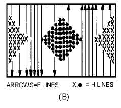
MODE NUMBERING SYSTEMS.—So far, only the most basic types of E and H field
arrangements have been shown. More complicated arrangements are often necessary to make possible
coupling, isolation, or other types of operation. The field arrangements of the various modes of operation
are divided into two categories: TRANSVERSE ELECTRIC (TE) and TRANSVERSE MAGNETIC
(TM).
In the transverse electric (TE) mode, the entire electric field is in the transverse plane, which is
perpendicular to the length of the waveguide (direction of energy travel). Part of the magnetic field is
parallel to the length axis.