2-48
Proper phasing between the pump and the input signal is crucial in this circuit. The electrical pump
action is simply a sine-wave voltage applied to a varactor located in a resonant cavity. For proper
operation, the capacitance must be decreased when the input voltage is maximum and increased when the
input voltage is minimum. In other words, the pump signal frequency must be exactly double the
frequency of the input signal. This relationship can be seen when you compare views (B) and (C). A
parametric amplifier of the type shown in figure 2-44 is quite phase-sensitive. The input signal and the
capacitor variation are often in the wrong phase for long periods of time.
A parametric amplifier that is not phase-sensitive, referred to as a NONDEGENERATIVE
PARAMETRIC AMPLIFIER, uses a pump circuit with a frequency higher than twice the input signal.
The higher-frequency pump signal mixes with the input signal and produces additional frequencies that
represent both the sum and difference of the input signal and pump frequencies.
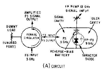
Figure 2-45A, is a diagram of a typical nondegenerative parametric amplifier with the equivalent
circuit shown in figure 2-45B. The pump signal (fp) is applied to the varactor. The cavity on the left is
resonant at the input frequency (fs), and the cavity on the right is resonant at the difference frequency
(fp-fs). The difference frequency is called the IDLER- or LOWER-SIDEBAND frequency. The varactor
is located at the high-voltage points of the two cavities and is reverse biased by a small battery. The pump
signal varies the bias above and below the fixed-bias level.
Figure 2-45A.—Nondegenerative parametric amplifier. CIRCUIT.