1-39
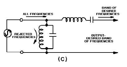
Figure 1-20C.—Components of a simple bandpass filter.
Band-Reject Filter
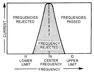
A band-reject filter circuit is used to block the passage of current for a narrow band of frequencies,
while allowing current to flow at all frequencies above or below this band. This type of filter is also
known as a BAND-SUPPRESSION or BAND-STOP filter. The way it responds is shown by the response
curve of figure 1-21. Since the purpose of the band-reject filter is directly opposite to that of a bandpass
filter, the relative positions of the resonant circuits in the filter are interchanged. The parallel-LC circuit
shown in figure 1-22, view (A), replaces the capacitor of figure 1-18, view (A). It acts as a band-reject
filter, blocking the passage of currents having frequencies at or near resonant frequency and passing all
currents having frequencies outside this band. The series-LC circuit shown in figure 1-22, view (B),
replaces the inductor of figure 1-18, view (B). If this series circuit is tuned, to the same frequency as the
parallel circuit, it acts as a bypass for the band of rejected frequencies. Then, the simplest type of band-
reject filter is obtained by connecting the two circuits as shown in figure 1-22, view (C).
Figure 1-21.—Band-reject filter response curve.