3-17
As the figure shows, the insulation gap formed by reverse biasing of the varactor is comparable to
the layer of dielectric material between the plates of a common capacitor. Furthermore, the formula used
to calculate capacitance
Where
A = plate area
K = a constant value
d = distance between plates
can be applied to both the varactor and the capacitor. In this case, the size of the insulation gap of the
varactor, or depletion region, is substituted for the distance between the plates of the capacitor. By
varying the reverse-bias voltage applied to the varactor, the width of the "gap" may be varied. An increase
in reverse bias increases the width of the gap (d) which reduces the capacitance (C) of the PN junction.
Therefore, the capacitance of the varactor is inversely proportional to the applied reverse bias.
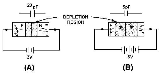
The ratio of varactor capacitance to reverse-bias voltage change may be as high as 10 to 1. Figure
3-15 shows one example of the voltage-to-capacitance ratio. View A shows that a reverse bias of 3 volts
produces a capacitance of 20 picofarads in the varactor. If the reverse bias is increased to 6 volts, as
shown in view B, the depletion region widens and capacitance drops to 5 picofarads. Each 1-volt increase
in bias voltage causes a 5-picofarad decrease in the capacitance of the varactor; the ratio of change is
therefore 5 to 1. Of course any decrease in applied bias voltage would cause a proportionate increase in
capacitance, as the depletion region narrows. Notice that the value of the capacitance is small in the
picofarad range.
Figure 3-15.—Varactor capacitance versus bias voltage.
In general, varactors are used to replace the old style variable capacitor tuning. They are used in
tuning circuits of more sophisticated communication equipment and in other circuits where variable
capacitance is required. One advantage of the varactor is that it allows a dc voltage to be used to tune a
circuit for simple remote control or automatic tuning functions. One such application of the varactor is as
a variable tuning capacitor in a receiver or transmitter tank circuit like that shown in figure 3-16.