Home
Download PDF
Order CD-ROM
Order in Print
Figure 3-9B.Tunnel diode energy diagram with 600 millivolts bias
Varactor
Neets Module 07-Introduction to Solid-State Devices and Power Supplies
Page Navigation
111
112
113
114
115
116
117
118
119
120
121
3-14
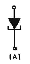
Figure 3-10A.—Tunnel
diode
schematic symbols.
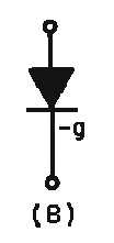
Figure 3-10B.—Tunnel
diode
schematic symbols.
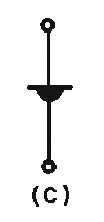
Figure 3-10C.—Tunnel
diode
schematic symbols.