7
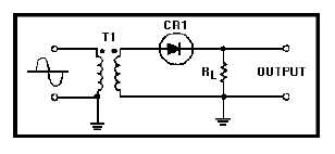
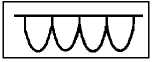
Figure 1B.—An electronic circuit.
IN ANSWERING QUESTIONS 1-52 THROUGH
1-55, REFER TO FIGURE 1-B.
1-52. What type of circuit is shown in figure
1-B?
1. Full-wave rectifier
2. Half-wave rectifier
3. Clipper
4. Clamper
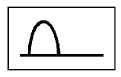
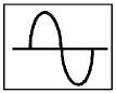
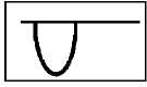
1-53. With the input shown, which of the
following outputs would be correct?
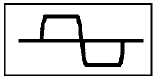
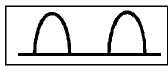
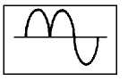
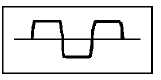
1.
2.
3.
4.
1-54. Which of the following outputs would be
correct with two alternations of the ac input
signal applied?
1.
2.
3.
4.
1-55. What is/are the purposes(s) of RL?
1. It limits the amount of current flow in
the circuit
2. It develops the output signal
3. Both 1 and 2 above
4. It maintains the proper bias on the
diode
THIS SPACE LEFT BLANK
INTENTIONALLY.