3-26
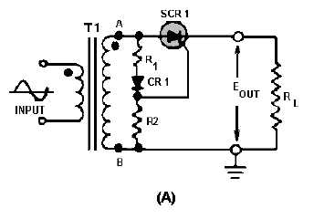
Figure 3-25A.—Comparison of SCR and TRIAC circuits.
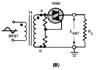
In the circuit shown in view B, with the TRIAC inserted in the place of the SCR, current flows
through the load resistor during both alternations of the input cycle. Because either alternation will trigger
the gate of the TRIAC, CR1 is not required in the circuit. Current flowing through the load will reverse
direction for half of each input cycle. To clarify this difference, a comparison of the waveforms seen at
the input, gate, and output points of the two devices is shown in figure 3-26.
Figure 3-25B.—Comparison of SCR and TRIAC circuits.