3-24
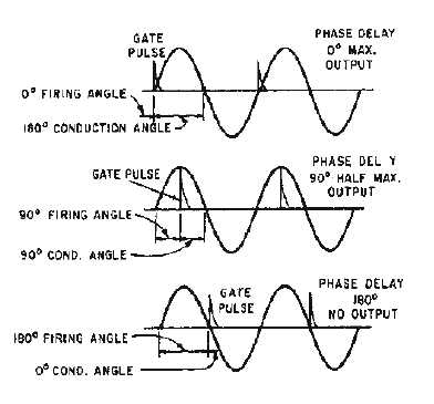
Figure 3-22.—SCR gate control signals.
When an ac power source is used, the SCR is turned off automatically, since current and voltage
drop to zero every half cycle. By using one SCR on positive alternations and one on negative, full-wave
rectification can be accomplished, and control is obtained over the entire sine wave. The SCR serves in
this application just as its name implies—as a controlled rectifier of ac voltage.
Q14. The SCR is primarily used for what function?
Q15. When an SCR is forward biased, what is needed to cause it to conduct?
Q16. What is the only way to cause an SCR to stop conducting?
TRIAC
The TRIAC is a three-terminal device similar in construction and operation to the SCR. The TRIAC
controls and conducts current flow during both alternations of an ac cycle, instead of only one. The
schematic symbols for the SCR and the TRIAC are compared in figure 3-23. Both the SCR and the
TRIAC have a gate lead. However, in the TRIAC the lead on the same side as the gate is "main terminal
1," and the lead opposite the gate is "main terminal 2." This method of lead labeling is necessary because
the TRIAC is essentially two SCRs back to back, with a common gate and common terminals. Each
terminal is, in effect, the anode of one SCR and the cathode of another, and either terminal can receive an
input. In fact, the functions of a TRIAC can be duplicated by connecting two actual SCRs as shown in
figure 3-24. The result is a three-terminal device identical to the TRIAC. The common anode-cathode
connections form main terminals 1 and 2, and the common gate forms terminal 3.


