2-19
Cathode-ray tubes are used in more applications than just television. They can be considered as the
heart of the many types of information.
Cathode-ray tubes have one function that cannot be duplicated by any other tube or transistor;
namely, they have the ability to convert electronic signals to visual displays, such as pictures, radar
sweeps, or electronic wave forms.
All CRT’s have three main elements: an electron gun, a deflection system, and a screen. The electron
gun provides an electron beam, which is a highly concentrated stream of electrons. The deflection system
positions the electron beam on the screen, and the screen displays a small spot of light at the point where
the electron beam strikes it.
THE ELECTRON GUN
The ELECTRON GUN is roughly equivalent to the cathodes of conventional tubes. The cathode of
the electron gun in the CRT is required not only to emit electrons, but also to concentrate emitted
electrons into a tight beam. In the electron tubes that you have studied, the cathode was cylindrical and
emitted electrons in all directions along its entire length. This type of cathode is not suitable for producing
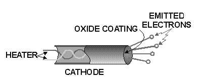
a highly concentrated electron-beam. The cathode of the CRT consists of a small diameter nickel cap. The
closed end of the cap is coated with emitting material. This is shown in figure 2-18. Because of this type
of construction, electrons can only be emitted in one direction. Notice that the emitted electrons shown in
figure 2-18 are leaving the cathode at different angles. If these electrons were allowed to strike the screen,
the whole screen would glow. Since the object of the electron gun is to concentrate the electrons into a
tight beam, a special grid must be used. This special grid is in the form of a solid metal cap with a small
hole in the center. The grid is placed over the emitting surface of the cathode and charged negatively in
relation to the cathode. The dotted lines represent the direction of cathode emitted electron repulsion, as
shown in figure 2-19. Since all emitted electrons leave the cathode (point C), their paths can be identified.
An electron attempting to travel from point C to point B (downward) will instead follow the path from
point C to point E to point P. Consider an electron leaving from C in the direction of point A (upward). Its
path will be curved from point C to point P by electrostatic repulsion. These curving electron paths are
due to the negative potential of the grid coupled with the high positive potential of the anode. The
potential of the anode attracts electrons out of the cathode-grid area past point P toward the screen. The
grid potential may be varied to control the number of electrons allowed to go through the control-grid
opening. Since the brightness or intensity of the display depends on the number of electrons that strike the
screen, the control grid is used to control the brightness of the CRT.
Figure 2-18.—CRT cathode.