2-20
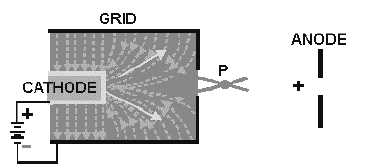
Figure 2-19.—Operation of the CRT grid.
The proper name, BRIGHTNESS CONTROL, is given to the potentiometer used to vary the
potential applied to the control grid. The control grid actually serves as an electron lens. It is this
electronic lens that you adjust when you turn up the brightness control on your TV set. Notice that the
effect of the grid is to focus the electron beam at point P in figure 2-19.
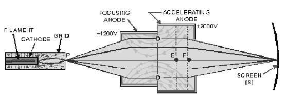
After passing point P, the electrons start to spread out, or diverge, again. Therefore, it becomes
necessary to provide some additional focusing to force the electrons into a tight beam again. This is done
by two additional positively-charged electrodes as shown in figure 2-20. The first electrode is commonly
called the FOCUSING ANODE. Generally, the focusing anode is charged a few hundred volts positive
with respect to the cathode. Electrons emitted by the cathode are attracted to the focusing anode. This is
the reason that they travel through the small hole in the grid. The second electrode, called the
ACCELERATING ANODE, is charged several thousand volts positive in relation to the cathode. Any
electrons approaching the focusing anode will feel the larger electrostatic pull of the accelerating anode
and will be bent through the opening in the focusing anode and will travel into the area labeled D. You
might think that once an electron is in this region, it is simply attracted to the accelerating anode and that
is the end of it. This does not happen. Because the accelerating anode is cylindrical in shape, the
electrostatic field radiating from it is equal in all directions. Thus, an electron is pulled in all directions at
once, forcing the electron to travel down the center of the tube. Then, the electron is accelerated into the
accelerating anode. Once it passes the mid-point (point E), it feels the electrostatic attraction from the
front wall of the accelerating anode, which causes it to move faster toward the front. Once the electron
reaches point F, equal electrostatic attraction on either side of the opening squeezes it through the small
opening in the front of the anode. From there, it is joined by millions of other electrons and travels in a
tight beam until it strikes the screen (point S).
Figure 2-20.—Electron-beam formation In a CRT.