1-31
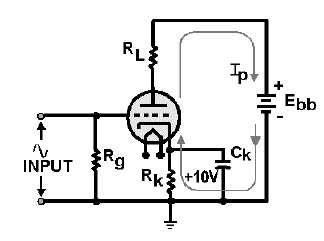
Figure 1-22.—Cathode bias.
The only difference between the illustrated circuit and the one used to demonstrate triode operation
is the elimination of the battery, Ecc, and the addition of circuit components Rk, the cathode-biasing
resistor; Ck, the cathode ac-bypass capacitor; and a grid resistor (whose purpose will be explained later).
When the tube conducts, current flows from the battery through Rk to the cathode, through the tube
to the plate, and through RL to the positive terminal of the battery. The current flowing through Rk will
cause a voltage drop across Rk. The bottom of Rk goes negative while the top goes positive. This positive
voltage at the top of Rk makes the cathode positive relative to the grid.
You may wonder what purpose Ck serves in this circuit. Ck serves as an AC BYPASS. Without Ck,
the bias voltage will vary with ac input signals. This is particularly troublesome in the higher frequencies
like those found in radio receivers. Rk, the cathode-biasing resistor, is used to develop the biasing voltage
on the cathode.
The input signal will be developed across Rg. You will read more about the circuit component later
in this chapter. Cathode-biasing voltage is developed in the following manner.
As we mentioned earlier, the bias voltage will vary with the input unless Ck, the cathode bypass
capacitor, is used.
To understand how the bias voltage will vary with an ac input signal, disregard Ck for the moment
and refer to figure 1-22 again.
Notice that under quiescent conditions, the voltage drop at the top of Rk is +10 volts. Now let’s apply
the positive-going signal illustrated to the left of the tube. When the positive signal is applied, conduction
through the tube will increase. The only trouble is that current through Rk will also increase. This will
increase the voltage drop across Rk, and the cathode voltage will now be greater than +10 volts.
Remember, at this time the plate is going negative due to increased conduction through the tube. The
combination of the negative-going plate and the positive-going cathode will decrease the electrostatic
attraction across the tube and lower the conduction of the tube. This will reduce the gain of the tube.
When the negative-going signal is applied, conduction through the tube decreases. Current through
Rk decreases and the voltage drop across Rk decreases. This causes the cathode to go more negative,
which tends to increase conduction through the tube. A negative-going signal is amplified by decreasing
plate current and allowing the plate to go positive (remember the 180º inversion.) Thus, increasing