2-27
PROCEDURE FOR TINNING COPPER WIRE WITH A SOLDERING IRON
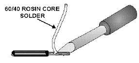
In the field, wires smaller than size No. 10 can be tinned with a soldering iron and rosin-core solder
as follows (see figure 2-27):
Figure 2-27.—Tinning wire with a soldering iron.
1. Select a soldering iron with the correct heat capacity for the wire size (see table 2-3). Make sure
that the iron is clean and well tinned.
Table 2-3.—Approximate Soldering Iron Size for Tinning
Wire Size (AWG)
Soldering Iron Size (Heat Capacity)
#20 - #16
65 Watts
#14 & #12
100 Watts
#10 & #8
20 Watts
2. Start by holding the iron tip and solder together on the wire until the solder begins to flow.
3. Move the soldering iron to the opposite side of the wire and tin half of the exposed length of the
conductor.
The tinned surfaces to be joined should be shaped, fitted, and then mechanically joined to make a
good mechanical and electrical contact. The parts must be held still. Any motion between the parts while
the solder is cooling usually results in a poor solder connection, commonly called a "fractured solder"
joint.
Q25.
What causes a "fractured solder" joint?
SOLDERING TOOLS
Many types of soldering tools are in use today. Some of the more common types are the soldering
iron, soldering gun, resistance soldering set, and pencil iron. The following discussion will provide you
with a working knowledge of these tools.