1-36
Q41. What electrical quantity is measured by an ohmmeter?
Q42. What other measurement can an ohmmeter make?
Q43. How is a series-type ohmmeter connected to the circuit being measured?
Q44. What is used to provide the ohmmeter with several ranges?
Q45. What area of an ohmmeter scale should be used when measuring circuits?
SHUNT OHMMETER
The ohmmeter described to this point is known as a series ohmmeter, because the resistance to be
measured is in series with the internal resistors and the meter movement of the ohmmeter. Another type of
ohmmeter is the SHUNT OHMMETER. In the shunt ohmmeter, the resistance to be measured shunts (is
in parallel with) the meter movement of the ohmmeter. The most obvious way to tell the difference
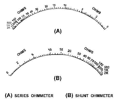
between the series and shunt ohmmeters is by the scale of the meter. Figure 1-34 shows the scale of a
series ohmmeter and the scale of a shunt ohmmeter.
Figure 1-34.—Series and shunt ohmmeter scales.
Figure 1-34(A) is the scale of a series ohmmeter. Notice "0" is on the right and "" is on the left.
Figure 1-34(B) is the scale of a shunt ohmmeter. In the shunt ohmmeter "" is on the right and "0" is on
the left. A shunt ohmmeter circuit is shown in figure 1-35.
In figure 1-35, R1 is a rheostat used to adjust the reading of the meter (full-scale deflection). R2,
R3, and R4 are used to provide the R 1, R 10, and R 100 ranges. Points A and B represent the meter
leads. With no resistance connected between points A and B the meter has full-scale current and indicates