1-38
MEGOHMMETER
An ordinary ohmmeter cannot be used for measuring resistance of multimillions of ohms, such as in
conductor insulation. To adequately test for insulation break down, it is necessary to use a much higher
potential than is furnished by the battery of an ohmmeter. This potential is placed between the conductor
and the outside surface of the insulation.
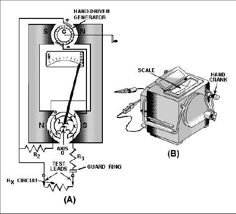
An instrument called a MEGOHMMETER (MEGGER) is used for these tests. The megger (fig.
1-36) is a portable instrument consisting of two primary elements: (1) a hand-driven dc generator, G,
which supplies the high voltage for making the measurement, and (2) the instrument portion, which
indicates the value of the resistance being measured. The instrument portion is of the opposed-coil type,
as shown in figure 1-36(A). Coils a and b are mounted on the movable member c with a fixed relationship
to each other, and are free to turn as a unit in a magnetic field. Coil b tends to move the pointer
counterclockwise, and coil a tends to move the pointer clockwise.
Figure 1-36.—A megger internal circuit.
Coil a is connected in series with R3 and the unknown resistance, Rx, to be measured. The
combination of coil, R3, and Rx forms a direct series path between the positive (+) and negative (-)
brushes of the dc generator. Coil b is connected in series with R2 and this combination is also connected
across the generator. There are no restraining springs on the movable member of the instrument portion of
the megger. Therefore, when the generator is not operated, the pointer floats freely and may come to rest
at any position on the scale.